
SJ60 Hall Joystick
Keywords:
SJ60 Hall Joystick
Classification
- Introduction
-
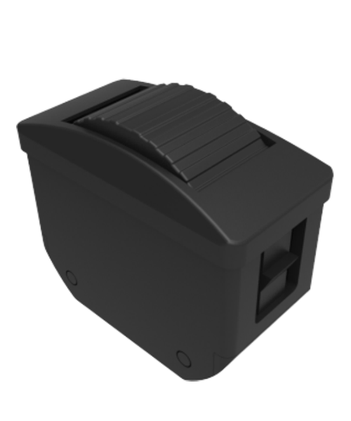
- Commodity name: SJ60 Hall Joystick
SJ60 series products are mainly used in cranes, loaders, forklifts, excavators, tractors, harvesters, etc.
SJ60 series products are mainly used in cranes, loaders, forklifts, excavators, tractors, harvesters, etc.
Product features: Using ergonomic principles, designed for the engineering machinery industry, non-contact Hall sensor and long Lifetime potentiometer two angular displacement detection methods, a variety of different types of handle upper end to choose. Number of buttons, location can be customized,Select CAN bus output
Operation method
1A single axis front and rear direction operation
2AP biaxial cross operating direction
2AC dual axis arbitrary operation direction
Micro Switch
L starting force 4.N
M starting force 5N (default)
H starting force 9N
output signal
Potentiometer type (supply voltage<36Vdc)
P021 2KO potentiometer, 0%~100% Vdc voltage output
P022 2KO potentiometer, 10%~90% Vdc voltage output
P023 2KO potentiometer, 25%~75% Vdc voltage output
P051 5KO potentiometer, 0%~100% Vdc voltage output
P052 5KΩ potentiometer, 10%~90% Vdc voltage output
P053 5KΩ potentiometer, 25%~75% Vdc voltage output
P101 10KΩ potentiometer, 0%~100% Vdc voltage output
P102 10KΩ potentiometer, 10%~90% Vdc voltage output
P103 10KΩ potentiometer, 25%~75% Vdc voltage output
Hall type (supply voltage 5Vdc)
H51 Single Hall per axis, 0.5~2.5~4.5Vdc voltage output
H52 Single Hall per axis, 0~2.5~5Vdc voltage output
H53 Single Hall per axis, 1.25~2.5~3.75Vdc voltage output
H54 Single Hall per axis, 1.0~2.5~4Vdc voltage output
H55 Single Hall per axis, 1.15~2.5~3.85Vdc voltage output
2H51 Redundant Hall per axis, 0.5~2.5~4.5Vdc voltage output
2H52 Redundant Hall per axis, 0~2.5~5Vdc voltage output
2H53 Redundant Hall per axis, 1.25~2.5~3.75Vdc voltage output
2H54 Redundant Hall per axis, 1.0~2.5~4Vdc voltage output
2H55 Redundant Hall per axis, 1.15~2.5~3.85Vdc voltage output
With conversion circuit
U21 power supply voltage 18~36Vdc, -10V~0V~+10V voltage output
U22 power supply voltage 18~36Vdc, +10V~0V~+10V voltage output
U23 power supply voltage 18~36Vdc, -5V~0V~+5V voltage output
U24 power supply voltage 18~36Vdc, +5V~0V~+5V voltage output
I21 power supply voltage 9~36Vdc, two-wire 4mA~12mA~20mA current output
I22 power supply voltage 9~36Vdc, two-wire 20mA~4mA~20mA current output
NA no analog signal output
CAN bus type (supply voltage 9~36Vdc)
J33 CAN2.0 bus output, source address is 33
J34 CAN2.0 bus output, source address is 34
J35 CAN2.0 bus output, source address is 35
J36 CAN2.0 bus output, source address is 36
Micro Switch
MS00 no micro switch
Ms12 with 4A front and rear position micro switch (not available for dual axis cross direction operation)
Upper end of handle
HA HA type handle upper end, no button at the top
HAS HAS type handle on the top, with buttons on the top
HD HD type handle upper end, no button at the top
HDS HDS type handle on the top, with buttons on the top
Upper end of HDR HDR handle, seesaw at top
KGDR has a safety switch with a seesaw button
KGDN has safety switch, no seesaw button
SS See the description of the upper end of the SS type handle.
Way out
D Dechi connector (CAN bus output only)
A amp connector
The main technical parameters
Potentiometer type
voltage
<36Vdc
Total resistance
2KΩ,5KO,10KΩ
Electrical angle
±18°
Median voltage
±18°~52% (relative to power supply voltage)
Median dead zone angle
±2.5°
Potentiometer loading maximum voltage
32Vdc
Potentiometer allows maximum power consumption
0.25W
Hall type
voltage
5.0±0.5Vdc
Supply current (rated supply current)
<11mA (per Hall sensor)
Limit allowable overvoltage
20Vdc
Reverse limit allowable voltage
-10Vdc
Output voltage linearity error
<±0.2V
Direction switch
load capacity
2mA@30Vdc
Starting angle
±5°
Contact resistance
<200O
With conversion circuit
Power supply voltage range
18~36Vdc(U21~U24)
9~18Vdc(I21~I22)Power consumption current
<20mA
Maximum output current
10mA (at standard voltage output)
Micro Switch
load capacity
4A@30Vdc (resistive load)
Service life
More than 30 million times (mechanical)
200,000 times (electrical)Insulation resistance
>100MΩ (500Vdc insulation resistance meter)
Starting angle
±3°~±5°
CAN bus type
voltage
9~36Vdc
CAN version
CAN2.0B
protocol
J1939
Wiring port
6-pin socket (Deutsch)
Mechanical parameters
Shake angle
±20°
Operation method
Spring automatic reset
Starting force
5N
Maximum operating force
11N
Limit force
>300N
Service life
>2 million times (potentiometer type) > 5 million times (Hall type)
weight
475g (no upper end)
Environmental parameters
Operating temperature
-30℃~+70℃
Storage temperature
-40℃~+85℃
Protection level
IP65 (above the installation panel)

Product size chart

Installation diagram

Recommend


Relevant products
Welcome to the consultation.
Please contact us at your convenience.
Contact
Add:Xirendang Industrial Zone, Liushi Town, Yueqing, Wenzhou.


Quick Navigation
SAF Coolest v1.3 设置面板 PGHSX-ZGGS-RESFE-ZZF
无数据提示
Sorry,当前栏目暂无内容!
您可以查看其他栏目或返回 首页